
Table of Contents
Access Control Smart J/JX
License– Maintenance Agreement
The use of this software requires a Vermont Systems license and annual maintenance agreement. Prior to implementing any process outlined in this document, please contact the Vermont Systems Sales department at 877.883.8757 or by email (sales@vermontsystems.com) to verify that you are authorized to use this software or to obtain a quote and approval.
Pre-Installation Checklist
This checklist defines the Customer’s and Vermont Systems' respective responsibilities when installing the Vermont Systems Access Control system. Because access control hardware can vary, you must consult with an electrician that specializes in circuit design and installation. You will also need to work with your Information Technology (IT) staff to discuss running CAT5e/6 cable to the access point(s). In addition, you must decide where the access control scanners will be located and how you will mount them.
Complete the fillable form .pdf checklist that follows, and return it to Vermont Systems.
Since access control readers are custom-made, we will not order the readers until the checklist is received. The Vermont Systems section lists Vermont Systems' responsibilities; after reading and understanding each item, check the box next to that item. The Customer’s Responsibilities section lists your responsibilities; check the box next to each item to acknowledge assuming responsibility for that item.
If you have any concerns or questions, contact Vermont Systems Customer Service via phone at 877.883.8757 or open a case in the Vermont Systems Support portal.
Your Name: ________________________________________________________
Your Organization: ________________________________________________________
Date: _______________
RecTrac Version: _______________
Access Control Checklist - Vermont Systems Responsibilities
Check the box next to each item to acknowledge having read and understood it.
- Vermont Systems provides the software that interprets a scan and allows access if the scan is valid.
- Vermont Systems will provide technical assistance to your chosen electric circuit and cabling installer.
- Vermont Systems will encode the Smart JX device with an IP address after discussing configuration options with your IT department.
- Vermont Systems will configure the Smart JX (if using this option) to ensure that bar codes and magnetic stripes read correctly.
- Vermont Systems provides phone-assisted or on-site configuration of the RecTrac access control software as quoted.
Access Control Checklist - Customer Responsibilities
Check the box next to each item to acknowledge having read and understood it.
- The customer will install and mount all hardware for the access control system, including the following:
- Decide whether you will supply power to the door strike or if the power will be supplied by the access control reader via POE (Smart JX only).
- Order Smart JX devices a minimum of 4 weeks in advance of installation.
- Install door strike/maglock or turnstile.
- Install Smart JX near the access control point, where your customers can reach it.
- Complete the connection between the Smart JX and the door strike or turnstile. An electrical contractor must design and physically complete this connection. If the door strike or turnstile does not have a built-in MOV (metal oxide varistor), the electrical contractor will need to build one into the circuit. If not using a Power Over Ethernet (PoE) Standard Smart JX, and the power to the contacts is greater than 30VDC and or greater than 500mA, the contractor will have to design the circuit with an additional relay between the smart JX and the door strike or turnstile.
- Obtain an updated diagram that outlines the circuit between the smart JX and the door strike or turnstile. Go to the International Bar Code(IBC) website (www.interbar.com) and click the support link. In the wiring category, download the PDF labeled SA/STA reader wiring (with RS232 or RS422interface).
- Provide one 120VAC power outlets. The Smart JX must be plugged into a 120 VAC power outlet. In addition, provide any power required by your turnstile or door strike.
Notes: If using a Power over Ethernet Hub/Switch and PoE Standard Smart JX or PoE Non-Standard Smart JXa power outlet is not needed for the scan devices.
100 Meters MAX distance communication using Ethernet cabling.
If using an Intelligent POE Switch device, it could extend the distance up to 200 meters.
- Connect CAT 5e/6 cable between a network hub/switch and the SmartJX.
As soon as all the connections have been made and power is supplied to the access point and the Smart JX, the customer must notify Vermont Systems so that a Connectivity Test can be performed approximately 4 weeks prior to your “live” date.
It is necessary that all access points are tested and pass the test. If you decide not to configure the software using phone training and you are planning on having a Vermont Systems installer on site, travel will not be arranged until all access points pass this test. If a Vermont Systems installer is on-site for the purpose of configuring your access device(s) software and wiring is incorrect and/or the test fails, the customer is responsible for all expenses incurred by that installer (e.g., time and travel).
Configuring a Smart JX Sprox JX Device
1 Download the Ibctcp44 utility.
- Open a web browser and go to http://www.interbar.com. Click on the Software link.
- Click on the Ibctcp44 link and save it to a local folder.
- When the download completes, browse to the location where you save the Ibctcp44.zip file and unzip it. The zip file will extract a setup.exefile.
- Right-click on the setup.exe and Run as Administrator.
- Follow the on-screen instructions during the installation process. This will install the Ibctcp44 software on your computer.
2 If you are installing multiple devices, prepare an organized listing of IP addresses and locations that correspond to each device. After configuring each device, be sure to label each clearly.
3 To begin the configuration in windows, go to Start • Programs • IBC. Run the Ibctcp44.exe utility program. You will see screens similar to the following screens, though IP Address, Port and other information may vary.


4 Click Local Network Search.Press F1 Start Search. You should see the default IP address of the smart JX/Sprox JX, the MAC address of the reader, the Reader Identification and the Ctrl Port.
5 Double-click on the first device listed. This will display the Program Reader screen.
- Click Get Parameters.
Note: If unable to connect to Qscan, go to Unable to Connect to Smart J DuringSetup.

6 Change the Reader IP Address, the Reader Subnet Mask and the Reader Gateway Address (if applicable) to values determined by your Network Administrator. Enter a unique name in the Identifier field to identify this specific Smart JX/Sprox JX.
7 Set the Operating Mode to "UDP."
8 Set the Speed to "Auto.”
9 Set the UDP send id option to "Yes."
10 Ensure that the IP Address in the Server Address field is NOT the same as the IP Address in the Reader IP Address field.
- This ip should point to the server that will be running access control, whether it is the local machine or whether it is hosted in another location. It should not be the same as the reader address.
11 Click Set Parameters. Once the new parameters are saved, you will receive the following message: “New Parameters have been set – You must Reboot (or repower) the reader for the new parameters to take effect.”
Click OK.
12 Click Reboot. Click OK.
Note: In the event this does not work, you can power-cycle the Smart JX physically by unplugging the Ethernet cable, waiting a few seconds and plugging it back in.
13 If using bar code access control configure the Smart JX by swiping the set % preamble found in the Smart Slot JX Series commands document (as well as in the Connectivity Test). An audible signal confirms that the bar code has been read and the device has been properly configured.
14 Repeat steps 6–13 for each SmartJX/Sprox JX device.
SmartJ/JX/ Hardware Installation
1 All CAT 5e/6 cable and power supplies should be installed and tested prior to installing the access control hardware.
2 Install the door strike(s) or turnstile(s).
Note: Vermont Systems strongly recommends connecting and testing all devices prior to permanently securing the devices to their final positions.
3 Install the Smart J/JX near the access control point where your customers can reach it. If using a proximity head, install the Sprox JX in the access panel.
4 If using a proximity head, you will need to mount it and connect it to the Sprox JX. (Refer to the Sprox J/JXto Proximity head wiring diagram.)
5 Connect CAT 5e/6 cable between the network hub/switch and the Smart J/JX/Sprox J/JX device. If using a PoEStandard Smart J/JX or PoE Non-Standard Smart J/JX, be sure to connect the CAT5e/6 cable to the powered ports on the PoE Hub/Switch or Power Injector.
6 Connect power to the SmartJ/JX/Sprox J/JX device.
Note: This step is not necessary if using a PoE Standard or a PoE Non-Standard Smart J/JX.
7 Complete the connection between the Smart J/JX/Sprox J/JX and the door strike or turnstile.
- An electrical contractor/engineer must design and physically complete this connection.
- If the door strike/turnstile doesn’t have a built-in MOV, the electrical contractor will need to build one into the circuit.
Note: If using a PoE Non-Standard or a Non-PoE Smart J/JXand if power to the contacts is greater than 30VDC and or greater than 500mA, the contractor will have to design the circuit with an additional relay between the Smart JX/Sprox J/JX and the door strike or turnstile.
8 After all the connections have been completed and power has been supplied to the access point and the SmartJ/JX/Sprox J/JX (if required), the customer must notify Vermont Systems so that the Connectivity Test can be performed.
- This test must be completed approximately four (4) weeks prior to your live operation date.
9. If you are installing weatherized units outdoors, be sure to seal the back side of the Smart JX to the mounting plate using silicon caulking, such as 3M 5200 or Life Caulk. This will ensure that water or moisture doesn’t cause damage to the internal wiring.
Access Control Diagrams
Sprox JX with Built-in NIC Diagram


Smart JX with Built-in NIC Diagram


PoE Standard Smart JX with Built-in NIC Diagram

PoE Non-Standard Smart JX with Built-in NIC Diagram


Smart JX Mounting Template

Series Commands
Smart Slot 'J' Series Commands
If using bar code access control, configure the Smart J by swiping the set % preamble found below. To do so, fold the paper so that the bar code will be read as it is swiped through the slot reader. (Note: Vermont Systems recommends a buffer of ½" around the ends of the barcode.) An audible signal confirms that the bar code has been read and the device has been properly configured.
Optionally, you can print a Smart J Configuration Card directly to a PVC card using the Template at the very end of this document, if desired.
|
Set % Preamble  Ì*%uap037*ÈÎ |
|
Factory Default  Ì*%00*pÎ |
SmartJ Readers Cannot Read ID Automation128 Barcodes
In the event, your SmartJ cannot read the IDAutomation128barcodes, perform the following steps. Generally speaking, you will know the unit is not reading the barcode because nothing will happen when you scan the card; it likely will not even emit a 'beep.;
Scan the barcodes below. In the event scanning the barcode fails, perform the steps listed.
|
To Enable Barcode 128 Reading
|
|
To Enable Check Digit in Barcode 128
|


1 Launch IBC 4.4.
2 Search for the R reader and double click on it.
3 Click Get Parameters.
4 Change the Mode to "Server."
5 Click Set Parameters.
6 Click Reboot.
7 Click on Server Connect on the left.
8 Enter in the readers IP address in the IP Address field, Control Port Number of "87" and a Port Number of "57." Click Connect.
9 Current Status should change to "Connected."
10 In the middle of the screen, there is a white box, click on it once to make sure the window is in focus and do the following:
· (F10 key)BO(enter Key)
· (F10 Key)BCE(enter key)
11 Then click Disconnect.
12 Go back to the search and double click on the reader again.
13 Click Get Parameters.
14 Change the Mode back to "UDP."
15 Click Set Parameters.
16 Click Reboot.
Smart Jx - UDP Mode Returns OK and Flashes Red
Vermont Systems has found that some Smart Jx units, when set to UDP mode, will start flashing red at seemingly random intervals. The units will read a card (you will see the visit in RecTrac), but the Smart Jx will flash green only for an instant. If you experience this:
1 Launch IBC 4.4.
2 Search for the Reader and double click on it.
3 Click Get Parameters.
4 Change the Mode to "Server."
5 Click Set Parameters.
6 Click Reboot.
7 Click on Server Connect on the left.
8 Enter in the readers IP address in the IP Address field, Control Port Number of "87" and a Port Number of "57." Click Connect.
9 Current Status should change to "Connected."
10 In the middle of the screen, there is a white box, click on it once to make sure the window is in focus and do the following (these are zero's):
- X1070(Enter Key)
11 There should be no response at all when you press <Enter>.
- If there is then something is wrong. Make sure the "X" is a capital and that there are no spaces in the command.
- Repeat until there is no response then go to Step 12.
12 Click Disconnect.
13 Go back to the search and double-click on the Reader again.
14 Click Get Parameters.
15 Change the Mode back to "UDP."
16 Click Set Parameters.
17 Click Reboot.
Connectivity Test
This test is required to ensure connectivity has been established outside of the RecTrac application prior to implementing Access Control from within it.
IBCTCP Utility V4.4
Run the test using the IBC TCP Utility.
1 In Windows, go to Start •Programs • IBC, to run the IBC TCP Utility V4.4. It will open to the UDP Connect page.
2 Change the IP Address to match the Qscan device you are testing.
3 Ensure the Receive Port Number is"57" and Data Port Number is "53002" at the defaults unless you changed them during the initial setup. Click Listen. The current status should change to "Connected."
4 You should be able to swipe or scan your access card at the device location. The card number will display in the white box below in red, following a carriage return (hex 0d).
5 Send commands directly to the device by typing the commands on the left into the white screen. The results on the right should occur.
Command |
Result |
|---|---|
]00<carriage return> |
Green Light On |
[00<carriage return> |
Green Light Off |
}00<carriage return> |
Red Light On |
{00<carriage return> |
Red Light Off |
!15<carriage return> |
Relay On |
*<carriage return> |
Relay Off |
6 The commands will show in black as you type. You can enter them one after the other or use the Clear Screen button at the bottom to start fresh before each one.

Access Control Setup in RecTrac
Perform all steps in this section on the workstation from which you will be processing Access Control.
Note: All file paths and screen/tab locations in this document refer to file paths and screen/tab locations as they appear in the standard, default Vermont Systems Design. Your setup and Design may vary.
Ensure VIC is installed
To operate Access Control, Vermont Integration Client (VIC)must be installed on the workstation from which you will run Access Control.
By default, a VIC profile should be linked at the Default Level of Hierarchy in RecTrac. To utilize this profile, you would install VIC as a Service on the Access Control Workstation.
Optionally, you can use the VIC.exe installation and link a separate VIC profile at the Workstation Level of Hierarchy on the workstation running Access Control. Running Access Control as both an executable and a service. The IBC 7000 is configured to send data to the Workstation that has the server address that was entered in parameters using the TCP/IP Utility.
Refer to VIC Installation with Windows Installer for step-by-step installation instructions for VIC, if necessary.
Create an Access Control Workstation
1 In RecTrac, search for and go to workstation Management. Click Add to add a new workstation. You will continue to the Workstation Update • Core Settings screen.
2 In the Workstation Name field, enter the workstation name exactly as it is identified in the Ttcp/ipUtility. Vermont Systems suggests copying the identifier field into the workstation name in RecTrac.
3 Enter a Description.
4 Click Save. Exit back to the main RecTrac menu.
Create and Link an Access Profile
1 Search for and go to Profile Assignments. Click Add to add a new profile.

2 Enter a Profile Code to describe the profile that is being configured with Access Control.
3 Expand Profile Type and select "Access."
4 Select the Default Subtype.
5 Enter a Description.
6 Click Create. You will continue to the Profile Update screen.

7 Enable the Start UDP Listening option.
8 Accept the default entry for Listen on UPD Port (57) or overwrite as needed. This is the server port on the TCP/IP Utility.
9 On the Access Control Monitoring group, select the workstations that will be viewed in the Access Control Monitor program. Traffic from workstations not in this list will not appear in the Visits DataGrid in the Access Control Monitor.
10 Click Save. You will be returned to Profile Assignments.
11 In Profile Assignments, link this Access profile at the Workstation Level of Profile Hierarchy, to the workstation from which Access Control will be run. This should be the workstation on which you just performed these steps.
12 While logged into RecTrac on the machine designated to run Access Control, and while successfully connected to VIC, select the Access profile and click Update.
13 Click the "Configure" button at the bottom of the screen that matches your VIC installation (Configure Service for Access Control or Configure EXE for Access Control). The process will run automatically.
14 Click Continue when prompted.
15 Exit completely out of RecTrac. Do NOT save the session.
16 Close your web browser.
17 Exit the VIC and restart it.
18 Log back into RecTrac on the workstation.
Create and Link an Access Relay Profile
1 In RecTrac, search for and go to Profile Assignments. Click Add to add a new profile.
2 Enter a Profile Code for your Access Relay profile.
3 Expand Profile Type and select "Access Relay."
4 Expand SubType and select "SmartJ."
5 Enter a Description.
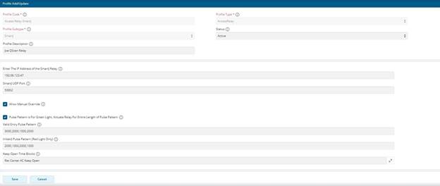
6 Click Create. You will continue to the Profile Update screen.

7 Enter the IP Address of the Smart J relay. This is the IP address that you assigned to the Reader using the TCP/IP Utility.
8 Enter the UDP Port that you assigned to the Reader in the Smart J Reader Data Port (UDP) Port field.
9 Select the Allow Manuel Override option if users will be allowed to manually open the Access Point via the Access Control Monitor program.
10 Select the Pulse Pattern is for green Light, Actuate Relay for Entire Length of Pulse Pattern option.
11 Enter your Valid Entry Pulse Pattern and Invalid Pulse Pattern values.
- This is the time value in milliseconds for which you wish the relay to toggle "on." For example, a flashing pattern 1000,2000,1000,2000,1000; would equate to 1 second on, 2 seconds off, 1 second on,2 seconds off, 1 second on
12 Click Save. You will return to Profile Assignments.
13 Link the Access Relay profile at the workstation Level of Hierarchy to the Access Control Workstation you created above. Repeat this step for each Access Point being setup
Create and Link a Visit Profile
Starting at Step 7, these steps need to be updated to reflect the new Visit Profile with the Access Control group. We'll need two (2) screenshots: One for the Core group (like the old one below) and one for the access Control group. Please be sure to use the Next Gen UI.
1 In RecTrac, search for and go to Profile Assignments. Click Add to add a new profile.
2 Enter a Profile Code for your Visit profile.
3 Expand Profile Type and select "Visit."
4 Expand SubType and select "Visit."
5 Enter a Description.
6 Click Create. You will continue to the Profile Update screen.

7 Open the Visit Pass List and select the Pass Codes that will be valid for this location.
8 Open the Daily Pass List and select the Daily Pass Code(s) that will be valid for this location:
9 Open the Location Code and select the Facility Location at which you will be processing Access Control.
10 Expand the BackGround/Access Control Visit Options group and enable the Select First Valid Pass option.

11 Expand the Miscellaneous Group, and open Access Ticket Daily Pass List. Select the Pass Codes that will be valid for this location. Likely this will be the same list of passes as you entered in the Daily Pass List above.
12 Select / Add the facility time block code to which you want to link this Access Relay profile. Selecting /Adding the time block will leave the relay in an open state during these selected hours. Note: You must set your beginning time to one minute before your desired open time and must ensure that RecTrac remains open in the browser on the VIC listening machine.
13 Fill in the remaining fields as necessary. Generally speaking, options for Prompts should be disabled. Use the help icon for field-level definitions, if needed.
14 Click Save when ready. You will be returned to Profile Assignments.
15 Link the Visit profile at the workstation Level of Hierarchy to the Access Control Workstation you created above.
Assigning Profiles
1 Access Relay and Visit profiles should be linked to the Access Control Workstation you created above.
2 Access and VIC profiles should be linked to the workstation on which you are processing.
Access Control Daily Processing in RecTrac 3.1
Note: Access Control does not require a login to function. So long as VIC is running on the designated machine, Access Control will function.
1 To monitor swipes at the access points, log into RecTrac on the workstation that Access Control is using to process requests. This is the workstation to which you linked the Access and VIC profiles.
2 To view Access Visits, search for and go to Access Control Monitor.
3 Manual override for the profiles linked in the Access Profile should display, as well as a Keep Open Override button and a DataGrid that displays recent Visits. The Keep Open Override button is a toggle button that will maintain the Access Relay in an open state when selected or a closed state when unselected.
Verify that 3.1 Displays the Photo
If selected, the Display Photos option on the Access device will display an individual’s photo (if a photo has been captured) for the person swiping into the access control point.

Troubleshooting
No Success with Connectivity Test
If you are unable to connect to your Smart JX via the IBCTCP Utility V4.4, check the following setup configurations. You should not be connected to your turnstile or door strike while performing the following steps.
1 From a DOS command prompt, attempt PINGing the device. If you are successful, unplug the CAT5e/6 cable from the Smart Jdevice and PING again. If you are still able to PING the IP, that specific IP is in use elsewhere on your network. You must configure the device with a different IP address.
2 Via the Ibctcp44 configuration software, verify that the correct IP addresses are assigned to each device.
3 Ensure the IP of the device and the IP of your machine are in the same Subnet mask.
4 If you are using a firewall client software, it must be disabled when attempting to connect to the device.
5 You cannot have an open connection to the Smart JX device within RecTrac. Make certain all other connections to this device are closed.
6 Once you can connect to the device, verify the connection with the test text files as explained in the Connectivity Test section. Also, make sure the card is read when swiping. If these tests do not work, there is a problem with the physical setup.
Other Problems
If you still cannot connect to the Smart JX device, below are more items to check.
1 Test the power to the Smart JX.
2 Test CAT5e/6 cable to ensure it is working and functional. To test this, bypass the installed CAT5e/6 cable and run a temporary CAT5e/6 cable from the switch/hub to the Smart JX. Test again. If this works, your installed cable is bad. If it does not work, the problem lies elsewhere.
Unable to Connect to Smart J During Setup
1 Highlight the Qscan you are trying to configure and click the Resolve Dupe button.
2 Enter the Qscan's new IP address and click Next.
3 Enter the Qscan's new subnet mask and click Next.
4 Enter the Qscan's password: 11111and click Next.
5 The Qscan will reboot.
6 Return to Configuring a Smart JX Sprox JX Device.
Electric Strikes vs. Magnetic Locks
Magnetic Locks
All magnetic locks (aka: mag locks) will work with DC current only, usually 12 to 24 volts, so never connect a magnetic lock to AC current at any voltage.
All magnetic locks are fail-safe, which means that they need a constant source of power to remain locked. If power is removed, the lock will open.
All mag locks are silent even when powered and locked. Electricians recommend at least 1200-pound pull magnetic locks for normal sized doors.
Caution is recommended regarding use of magnetic locks with respect to fire and smoke safety. Always check Local Authority Having Jurisdiction (LAHJ) during installation planning.
Electric Strikes
Electric strikes are often used for “buzz in” type systems. They can be 12, 24, or even higher voltage and they can take AC or DC current or some both.
They may be fail-safe or fail-secure. A fail-safe electric strike needs power to keep it locked, whereas, a fail-secure strike remains locked even without power.
Fail-secure is the most common type used. A fail-secure strike remains locked from the outside even if no power. For egress or getting out, a door knob or lever on the lock allows for safe exit.
If you need the “buzzer” sound, select an AC strike and AC power source or transformer. If you do not want the “buzzer” sound, select a DC power source or transformer. The DC strike is almost silent when it releases, except for a slight “click” sound.
If you want to use a DC strike or magnetic lock, but still want the “buzzer” sound, you can connect a tiny buzzer in parallel between the power supply and the electric strike or magnetic lock to make buzzer sound when the lock releases.
Source: The Keyless Lock Store.